

TAOKE EMS (Model TK-EMS001) is TAOKE’s (Dongguan Taoke Electronics Co., Ltd.) new-generation intelligent monitoring and energy-management product for the energy-storage market. It integrates multiple industrial communication interfaces and is compatible with mainstream protocols such as Modbus RTU / TCP, enabling unified access, real-time data acquisition and centralized control of PCS, BMS, HVAC / liquid-cooling units, smart meters and anti-backflow meters. With a local Qt touch GUI on a stable Linux platform, a remote Java management console and a cross-platform mobile APP (Android + iOS), it delivers local monitoring, remote management and mobile O&M in one system.
1. Product Overview
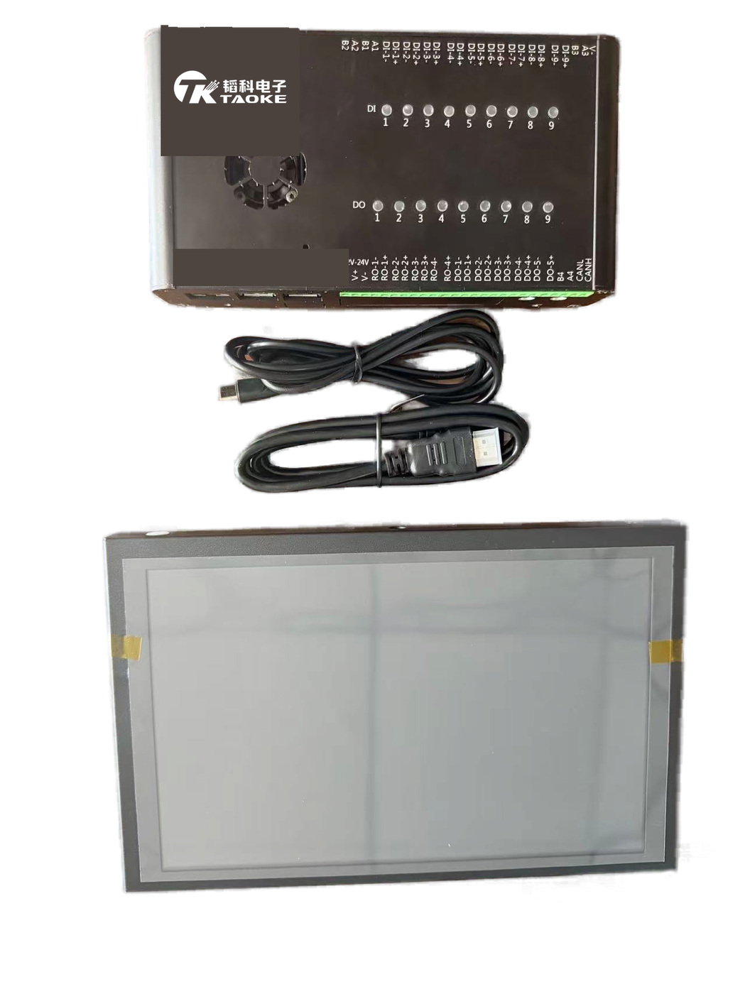
TAOKE EMS is a highly integrated, powerful local monitoring and energy-management unit. It runs on a development board with 64 GB storage and 4 GB RAM under Ubuntu (Linux); the front end is a Qt-based GUI and the back end talks to storage equipment over Modbus RTU / TCP, syncing with a Java backend via HTTP and MySQL for cloud upload, remote strategy dispatch and multi-terminal coordination.
Key capabilities: multi-device access (PCS, BMS, HVAC, meters — freely configurable in quantity), real-time monitoring, battery protection, power limiting, charge / discharge scheduling, local GPIO control, system self-check, remote management, data synchronization and mobile APP O&M.
Core Hardware
| Item | Specification |
|---|---|
| Model | TK-EMS001 |
| Storage | 64 GB |
| RAM | 4 GB |
| OS | Ubuntu (Linux) |
| Display | 10.1″ touch screen (HDMI + TOUCH) |
| Protocols | Modbus RTU / TCP, HTTP, MySQL |
| Local UI | Qt touch GUI (CN / EN switch) |
| Remote / Mobile | Java console + APP (Android / iOS) |
Product Photos
2. Software Architecture
The software is organized in three layers and integrates with a cloud Java backend for a clear, extensible and stable architecture:
- Device Communication Layer: talks to devices over Modbus RTU (RS485) or Modbus TCP; serial traffic is handled by an independent Python process exposing an HTTP interface for stability and isolation.
- Core Service Layer: a multi-threaded C++ module managing device objects, periodic acquisition, parsing, storage and control logic for fast response.
- HMI Layer: a Qt-based, touch-optimized GUI with CN / EN switching for field operators.
- Java Backend: runs on a remote server / cloud, exchanging data with the local unit over HTTP API and MySQL for sync, remote configuration and historical storage.
3. Core Function Modules
1. System Self-Check
On startup performs a full-link self-check (PCS / BMS / cooling / meter comms, server link) with a progress bar; results listed as “success / fail” with failed items highlighted and linked to logs; supports “re-check” or “skip” for both troubleshooting and emergency flexibility.
2. Real-Time Dashboard
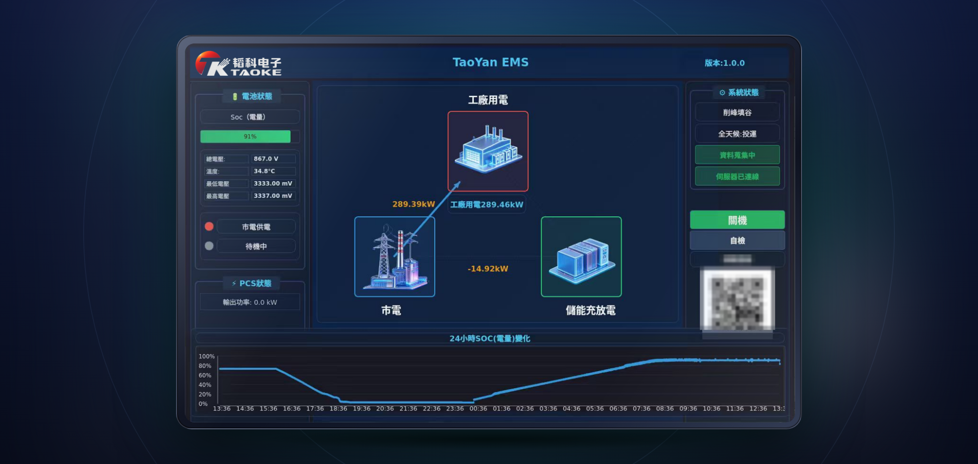
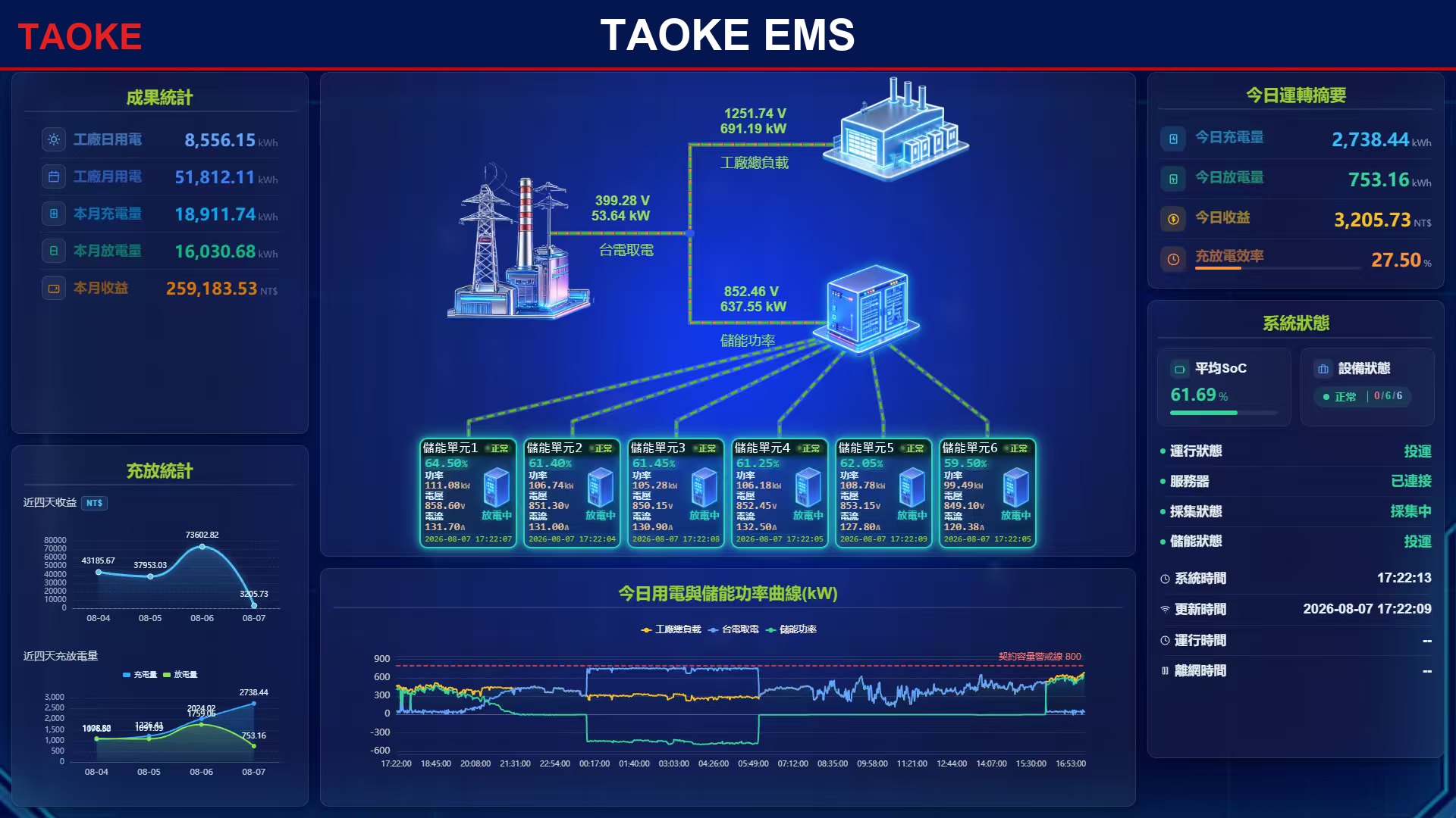
Central “grid – plant load – storage” topology shows live power flow (kW); left panel battery / PCS status, right panel strategy, commissioning, acquisition and server-link status; 24 h SOC trend; idle timeout (30 s–5 min) auto-return to dashboard and login authentication (user + password).
3. Multi-Device Acquisition
PCS (mode / frequency / 3-phase V&I / IGBT temp), BMS (SOC / SOH / pack voltage / cycles / cell balance), liquid cooling (pump / compressor / supply-return temp), meters (storage / anti-backflow, active-reactive power / PF / energy) with multi-device switching and color-coded key values.
4. Battery Protection
Threshold-based protection on SOC, voltage and temperature; a backend task checks every 5 s and, on trip, sends a 0-power command to the PCS and logs the event to prevent over-charge / over-discharge.
5. Power Limiting
Dynamic power control anchored on the transformer red-line (e.g. 500 kW): reads the anti-backflow meter in real time and adjusts storage charge / discharge when total power exceeds the line, preventing transformer overload and backflow; SOC-based limiting also supported (e.g. >95% limit charge, <5% limit discharge).
6. Charge / Discharge Scheduling
Up to 10 charge + 10 discharge time-window schedules for time-of-use peak shaving; all scheduled commands are intercepted and validated by the higher-priority battery / red-line / anti-backflow safety logic.
7. Local GPIO Control
9 digital inputs (DI) for e-stop, fire, water-leak, door and surge safety interlocks; 9 digital outputs (DO) drive run / alarm lamps, fans, trip and close / open relays; pin levels shown live in red / green.
8. System Configuration
Idle-return-to-dashboard timeout (1–60 min) and global acquisition period (1–3600 s) configurable per site, balancing real-time data and system performance.
9. Communication Interfaces
PCS over Ethernet Modbus TCP; BMS / HVAC / meters over RS485 Modbus RTU; RS485 via USB or on-board UART handled by a Python serial server (port 8081) and forwarded over HTTP; WiFi supported.
10. Alarm & Monitoring
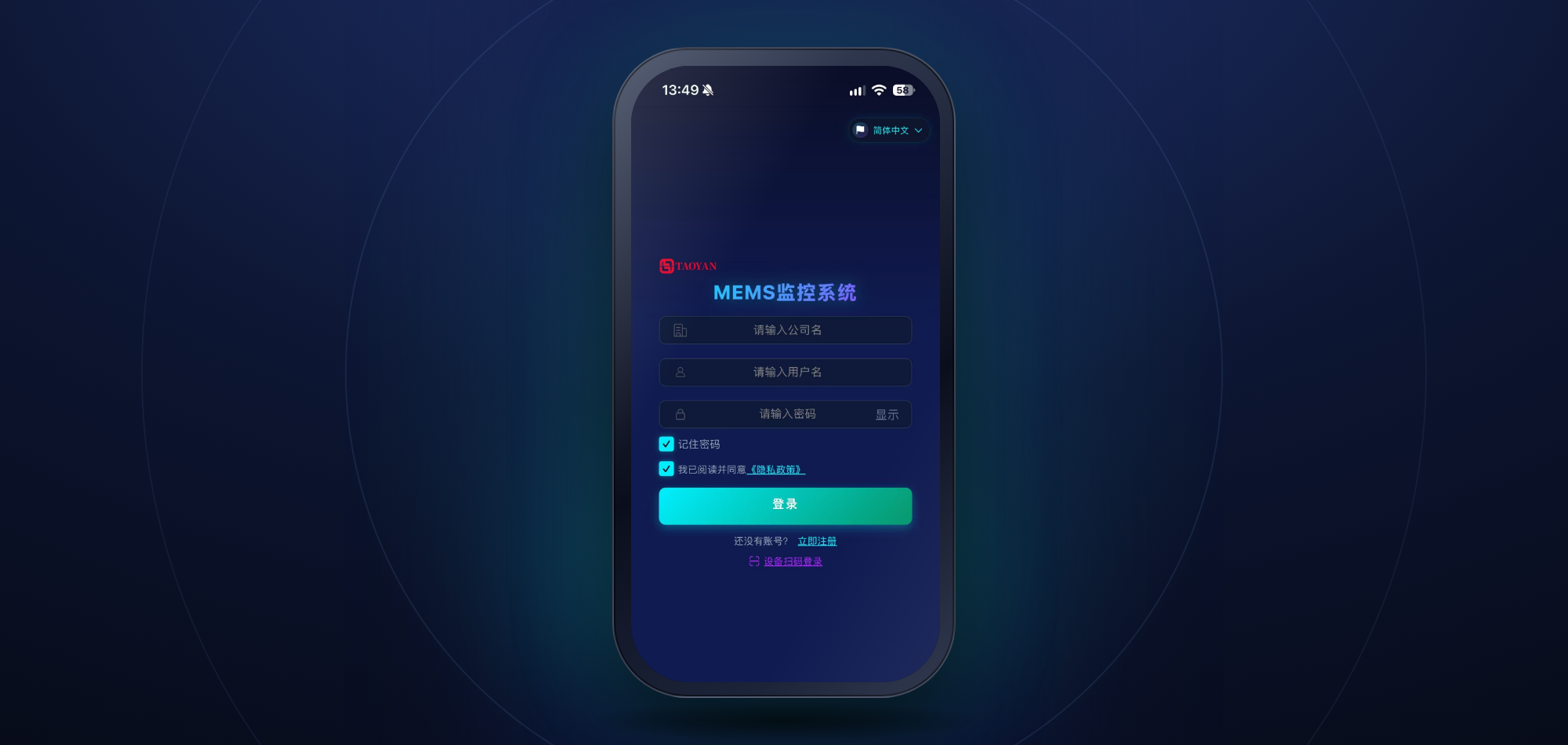
Web console + mobile APP (Android / iOS) for history queries, configuration, strategy dispatch and mobile O&M anytime, anywhere.
4. Communication Interfaces
| Device | Physical | Protocol |
|---|---|---|
| PCS | Ethernet (TCP) | Modbus TCP |
| BMS | RS485 | Modbus RTU |
| HVAC / Liquid cooling | RS485 | Modbus RTU |
| Meter / Anti-backflow | RS485 | Modbus RTU (DL/T645) |
Wiring Diagram
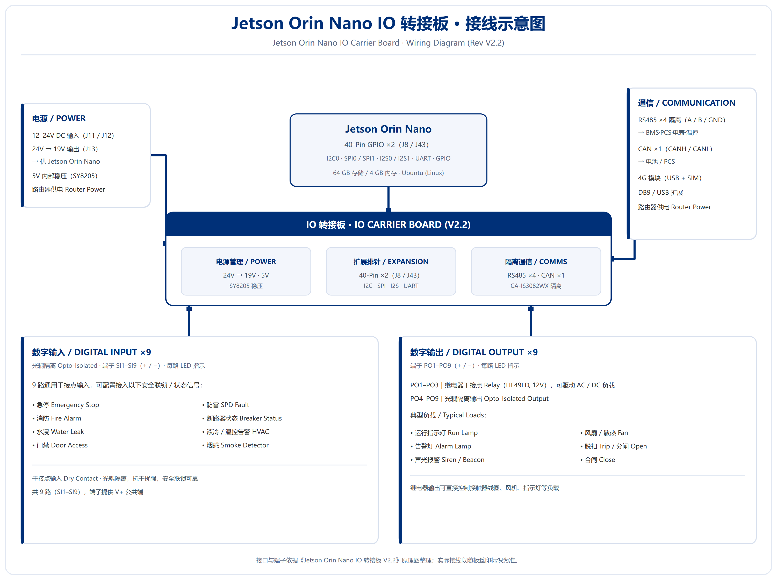
The diagram below shows the interfaces and typical wiring of the IO Carrier Board (V2.2): 12–24V DC input and 24V→19V output for the Jetson Orin Nano; four isolated RS485 ports (for BMS, PCS, meter and HVAC); one CAN port; nine opto-isolated digital inputs (DI) and nine digital outputs (DO, with PO1–PO3 as relay dry contacts); plus two 40-pin expansion headers.
5. Typical Applications
- Industrial & commercial peak shaving: TOU-based schedules charge off-peak and discharge peak, cutting electricity cost and smoothing load to ease transformer capacity.
- Microgrid stability: coordinates PV, storage and diesel genset for seamless island / grid-tied switching and resilient critical-load supply.
- PV-storage-EV charging: prioritizes PV consumption, stores surplus and discharges on shortage / peaks while feeding stable power to chargers.
- Backup & emergency power: monitors grid and rapidly switches to battery discharge on outage to keep hospitals, data centers and other critical loads running, with full battery protection to extend life.
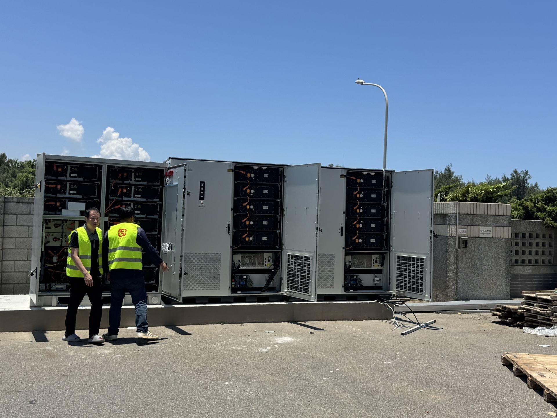
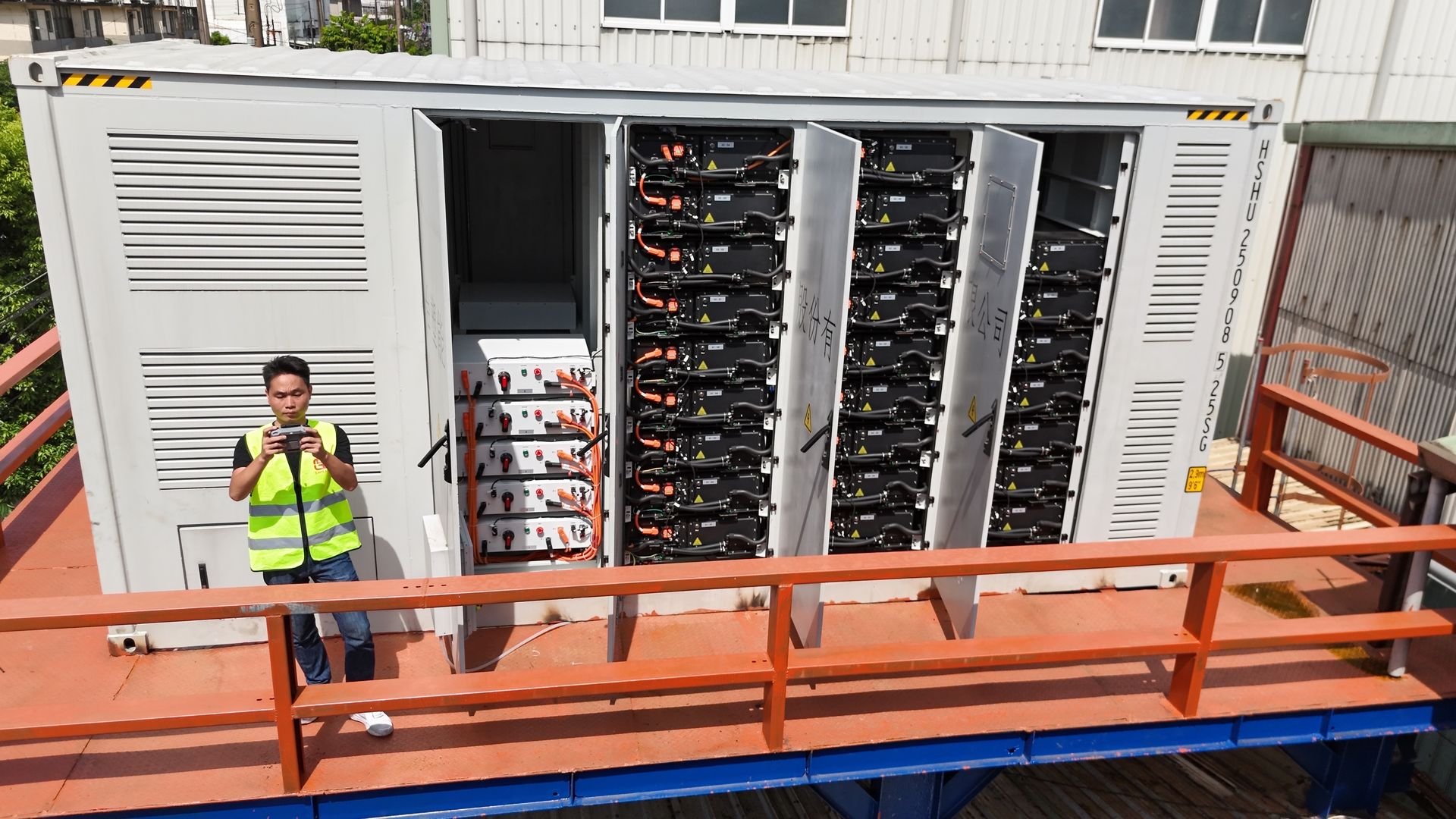
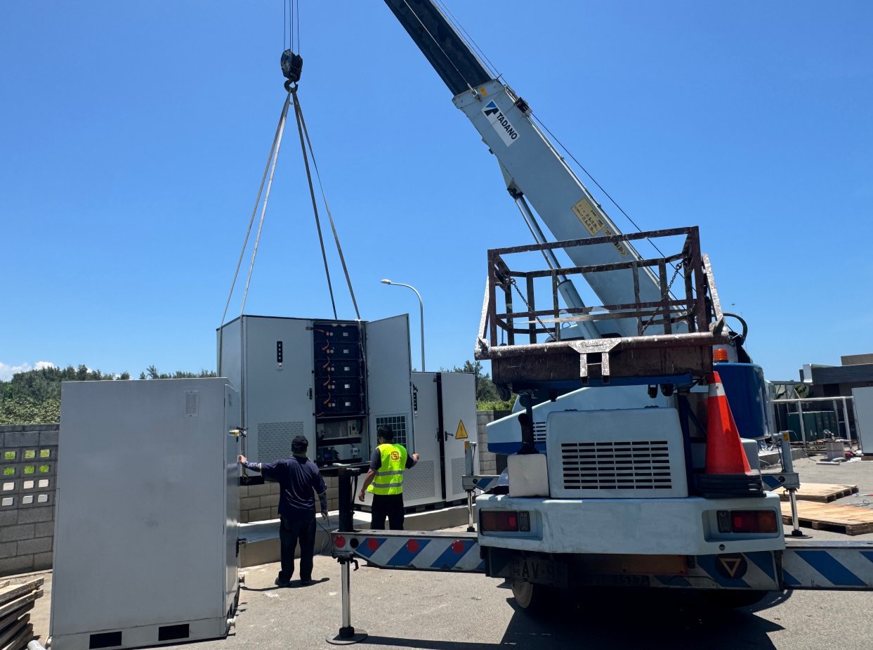
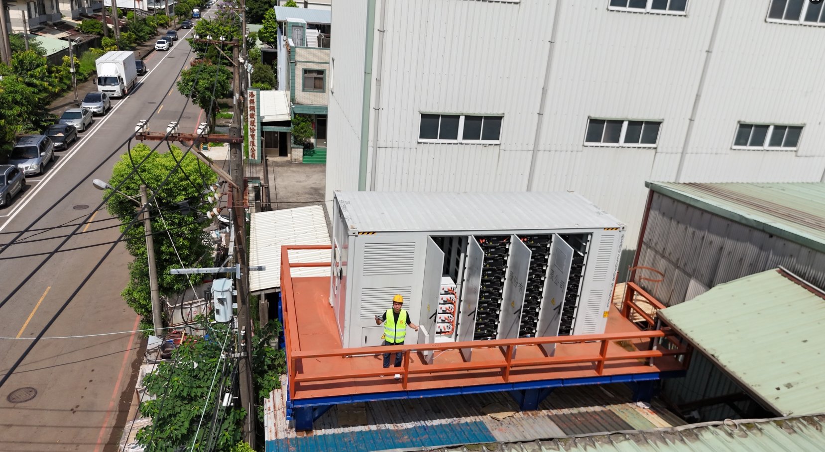
On-Site Project Photos
6. Manufacturer
Dongguan Taoke Electronics Co., Ltd. (TAOKE) independently develops and delivers this product. The company focuses on embedded software/hardware, industrial automation and energy-storage solutions, providing one-stop services from hardware design and software development to system integration, and highly customized energy-management and automation solutions per customer needs.
Brand note: TAOKE (Dongguan Taoke Electronics Co., Ltd.) and TAOYAN (Dongguan Taoyan Electronics Co., Ltd.) are the same company; the EMS system, hardware products and project-delivery materials shown here are presented under the unified TAOKE brand. Unified company address: No. 13 Kangle Road, Hengli Town, Dongguan, Guangdong, China.